Please follow the written guide or video below to learn how to assemble your Athena NC100 or 200 Electronic Scoring Target:
As of May 2024, all new Athena ESTs ship with our new pulley style mechanical lift.
Thank you for choosing the Athena NC100/200 System!
Before you begin, ensure you have all the parts listed for the initial setup.
|
|
Parts Included for Initial Setup: •1 × Electronic Scoring Target (EST) •1 × EST Power Adapter •1 × Red/Green Lights •1 × Mirror •1 × 7/16" or 11mm wrench •1 × 5ft long Square Rod (NC W/Lift Models) •1 × Rod Mounting Hardware (NC W/Lift Models) •2 × Rod Mounting Brackets (NC W/Lift Models) •1 × Camera Arm •1 × Base Mounting Hardware (NC W/Lift Models) •1 × Wooden Base board (NC W/Lift Models) |
|
Recommended for Initial Setup: •1 × Surge protector •1 × Level and Flat surface |
|
Assembly Instructions: |
|
Caution: Do not use power tools on the EST unit. Assembly may require more than one person. Use the correct power supply (supplied) on the EST unit for proper operation. Place the EST Unit on a level and flat surface for best results. |
|
Base Assembly: 1.Secure a reasonably flat workspace. 2.Align Rod Mounting Brackets, as shown, to ensure proper alignment. 3.Use hardware from the bag labeled “Base” . 4.Identify the bottom of the wooden Base with recessed drill holes. 5.Place a single flat washer on each bolt and insert into the bottom side of the wooden Base. 6.Affix Rod Mounting Brackets onto the top side of the wooden Base. 7.Place a split washer and a nut on the bolt. 8.Securely fasten nuts and bolts on the Base assembly. |
 Base bolt locations
 Base Bolts in bag
 Recessed holes, bottom of baseboard
 Installing Bolts with washer through base
 Mounting the bracket
 Split washer and nut |
Rod Assembly: 1. Place the square Rod into the Base assembly brackets, aligning the holes. 2. Use hardware from the bag labeled “ROD”. 3. Insert 4 bolts into the square Rod's pre-drilled holes through to the Base assembly brackets. 4. Affix square Rod using the split washers and nuts. 5. Securely fasten nuts and bolts on the Rod assembly. 6. Ensure all nuts and bolts are securely fastened to the Base and Rod assemblies before continuing.
|
 Aligning Square Tubing Rod with base assembly
 ROD Bolt bag
 Attaching Rod to Base using Bolts
 Securely fastened assemblies |
Power Adapter Assembly: 1. Slightly loosen the Power Adapter Bracket to slide it down the Square Rod. 2. Slide Power Adapter Bracket onto square rod, ensuring the J-shaped Power adapter mount faces up and outward of the assembly. 3. Measure about 10 inches from the wooden Base to the underside of the bottom bracket. 4. Tighten bottom bracket till split washers are flat. Do not overtighten on plastic parts. 5. Re-measure and adjust accordingly.
|
 Loosening the Threaded Rod Bottom Bracket
 Installing Bracket to face outward from Base
 Slight Tighten to keep in place
 Tighten Nuts and Bolts appropriatley |
Mounting the Target Head: 1. Be cautious not to drop the NC100 unit. This may be easier with 2 people, but can also be done by a single person. 2. First place the lower clamp which holds the power supply onto the pole. Tighten it a little above halfway up the pole to allow the target head to rest on it while you are working. 3. Align the top mount which holds the cables routed through its different pulleys as shown in the image to the right. 4. Loosen the nut on the front of the top mount which has the terminated steel cable attached to its bolt. 5. Slide the top mount onto the pole in the proper alignment, approximately 3-4cm down from the top of the pole. Then retighten the front nut to secure the mount to the pole. 6. Loosen the lower clamp you are using to hold the target head in place, and retighten it towards the bottom of the pole. 7. The target head is now safe to hang on its own. Carefully let it down until the cable takes up slack. If top mount holding the target head seems not tight enough to hold it in place, double check both the front bolt you tightened earlier, and also the rear bolt which has a pulley on it. You may need to remove the cap nut and pulley to access the nut underneath to tighten it slightly. 8. Remove the black spool cover. DO NOT do this unless the the target head is hanging freely with tension on the cable or unless you are holding the cable on the spool. 9. If the cable flies off of the spool, don't fret. Watch the video at the bottom of this page to see how to respool it.
|
 Attaching the lower mount at this height can hold the target head in place while working
 The top mount should be aligned as shown here
 Attach the top mount by tightening the front bolt on the mount
 Remove the black spool cover ONLY IF the target head is hanging freely or you are holding the cable on the spool. Needs to be removed before operating the lift. |
Camera Assembly: 1.Use hardware attached to the Camera Arm. Remove the bolt. Note: install can be easier if the bolt and nut are flipped so that the bolt is within the provided hex cutout of the camera arm hinge. 2.Carefully place the camera arm against the Target without damaging cables. 3.Align camera arm holes with mounting holes on the target frame and affix using the bolt, washer, and nut. 4.Tighten bolt or nut until snug. Do not overtighten. 5.Connect the Camera LED power wire to the dual prong connector on the top LED strip. 6.Remove plastic lens cover from the Camera. Wipe clean using a clean microfiber cloth. |
 Hardware preinstalled on camera arm
 Bolt and nut flipped for simpler installation
 Installing Camera arm w/Bolt on Target
 Tightening components till snug
 Camera LED cable needs installed to Front LED board
 Properly connected LED power pin
 Double checking the camera arm bolt and LED power pin
 Removing the plastic lens cover |
XO Red/Green Light Assembly: 1. Inset the light assembly into 2 slots on the back of the target frame. One side generally slides in easy, and the other side will need pressed carefully down to sit flush. 2. Properly attach the connecting cable from behind the NC100 unit to the bottom of the light assembly. 3. Peel off the plastic protective cover on the mirror. 4. Slide the mirror into the 45 Degree slot above the light board.
|
 X/O Frame Tabs being slid into main frame notches
 Connector under X/O board
 Installing Mirror |
Aiming Masks, Loading the Paper-Roll, and Power: |
|
Rear Aiming Mask: 1.Rotate the 2 cam locks towards the EST Front to unlock the mechanism 2.Insert Rear Aiming Mask between the frame and paper tensioner, ensuring the paper stays within the cutout guide. |
 Right Side Cam Lock
 Installing the rear aiming mask |
Loading the Paper Roll: 1. Locate the conical spring-loaded Paper Holders at the top of the unit. 2. Remove plastic caps from the Paper Roll. 3. Cut the sticker binding the edge of the Paper Roll with a sharp blade. 4. Install Paper Roll onto spring-loaded Paper Holders. 5. Feed the Paper Roll in front of the rear aiming mask and through the top and bottom guides of the pressure plate till it touches the rubber roller of the Tape Feed.
|
 Paper Holders at top of Target
 Removing Plastic end caps
 Cutting edge of paper roll
 Feeding Paper through guides to rollers
 Properly Fed Paper roll, Front aiming mask to be installed after feeding tape
|
Power and Paper Roll Feeding: 1.Ensure Power and Tape Feed Switches are in the Off position. 2.Plug power brick into the bottom of the NC100 before plugging the power cable into the outlet. 3.Place the power adapter brick into the holder on the bottom bracket. 4.Power on the EST. 5.Align the paper roll with the Feed rollers. 6.Switch On the Paper feed roller and feed the paper roll through till taught. 7.Switch off the paper feed roller. 8.Trim excess by pulling paper roll against the trim blade. |
 O means Off,
 Power Plug location, underside of EST
 Power Brick holder at bottom of Rod
") Powering On (-)
 Feed the paper roll through the feed rollers using this switch
 Paper roll feeding through, paper cutting blade in front, pull paper against this to tear |
Front Aiming Mask: 1. Insert front aiming mask in front Paper roll, utilizing the mask guide to ensure alignment. 2. Rotate Locking cams towards the rear of the EST to secure paper tension. |
 Installing Front Aiming Mask
 Ensuring paper alignment before locking
 Locking Down cams and ensuring Paper tension
 Properly installed Mask |
Height Alignment: •After the EST is fully assembled, measure the aiming bowl height from flat ground level. Ensure it is approximately 1.4 meters or 55.1 inches from a level ground.
•At Standing position the allowable tolerance is up to 2 inches (5cm) up or down.
•Kneeling or Prone have an allowable tolerance of up to 4 inches (10cm) up or down.
•If the height is not set within these tolerances, one may loosen the front nut on the top bracket to properly adjust the EST's height up and down. Re-tighten any loose nuts or bolts once complete.
|
 Center of Aiming Bull in Standing measuring roughly 55 inches
|
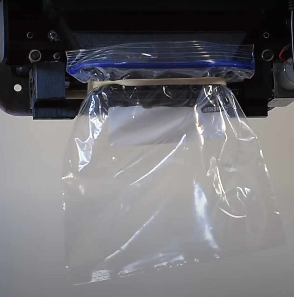
Pellet Collection Bag: •Secure the pellet collection bag using an elastic band underneath the unit at the pellet collection funnel.
•Replace the lead collection bags as necessary. Dispose of lead collection bags according to your local or state regulation.
|
|
Setting Up Your Monitor |
|
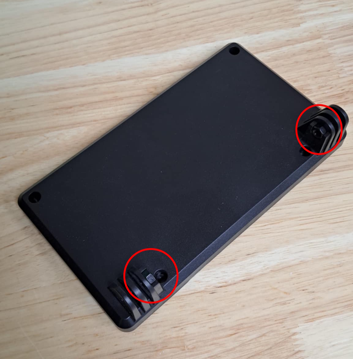
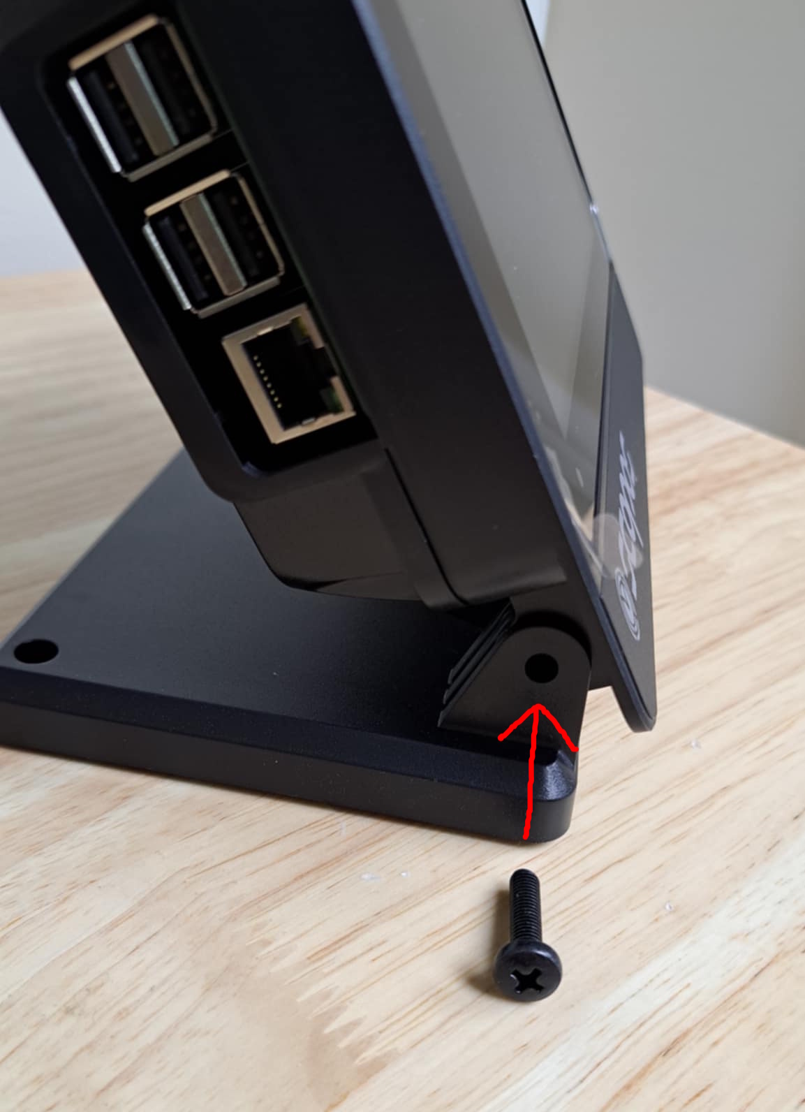
1. The nuts should be already glued in place in the base. If not, set them back into their proper location shown and then insert the monitor into the base. 2. Align the holes and then insert the bolt from the outside, keeping the monitor flat to prevent the nuts from falling out of their socket. Screw in the bolt until it is tight, but still loose enough to be able to swivel the monitor.
|
|
Connecting to the Athena Network:
For Athena for Clubs, see the following article to learn about the Take Ownership process, which will tie your Targets, Monitors, Displays, and Range Timers into your Range: https://support.scopos.tech/taking-ownership-of-est-units-.html
For Athena at Home, see the following to learn how to use the Take Ownership process to tie your Target and Monitor into your account on Rezults: https://support.scopos.tech/linking-your-at-home-target-an.html Additional Information:•For more information and detailed instructions, visit Athena Network Requirements. |
|
If you have any questions, contact our support team at support@scopos.tech or call (703)-596-0099.
|
|


Assembling Athena NC Target
Also See: